
|
|||
WELDING
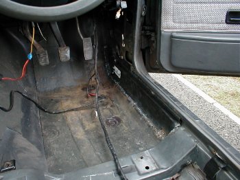
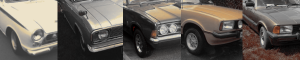
| Act One. You can see from the picture (fig 1) there isn’t much left of the offside inner sill where it joins the foot well, however the rot only goes as far back as the cross member, so I have decided to cut the new inner sill and weld up to the cross member. |
 |
| I have cut out the rest of the old sill as it impedes the positioning of the new one. I have left the top of the old sill where it joins the outer sill under the beading. I ground all the metal where the sill meets the body to ensure a good weld. However even with a 110mm grinder some areas aren’t as clean as they should be. I held the sill in place with a G clamp (I will have to get some mole grips soon) and tack the sill to the cross member. Moving the G Clamp along the seam between the inner and outer sill I weld along the floor of the car. |
 |
| Something’s not right, the welding gun is jumping and I cannot get a decent run. I increase the speed of the wire, its improved but still the gun is jumping. Then I blow a hole in the floor, a blast of sparks and a half decent four-inch run is achieved. I need to set this mig welder up properly. I continue with the weld along the floor and although this pigeon has severe diarrhea the weld is constant and firm. I go back and fill in the hole blown earlier. A few slugs with the hammer manipulates the top of the sill into position in the foot well. I decide to weld the inner and outer sills where they meet under the beading. Not a chance, the mig seams to be reluctant to weld anything and just insists on depositing blobs of wire wherever I make contact. I resort to the arch welder. Due the there being the original inner and outer sill still present at the seam and the new inner sill nestling parallel to them there a lot of metal to weld. The stick make sort shrift and ever levels the incorrect height difference between the old and the new. A bit a grinding and the weld is complete. Opps!! there goes the end of my index figure. Touching a grinding disk whilst its still in motion is my first H & S lesson. A cup of tea a strip of band-aid and some Germoline and I’m back in action. I finish off tacking the top of the new sill onto the sidewall of the foot well. Due to the indentations of the panel I can only tack in places. Before I Started this project I asked the local MOT station how much welding should be done when replacing panels, they informed me any replacement panel should be welded along the entire edge, this needs some thought. |
| Act Two.
|
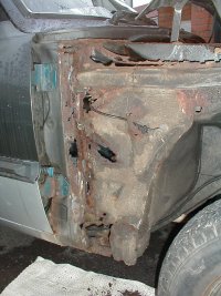 |
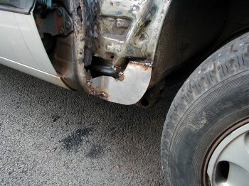
| The bottom the inner wing where the jacking point is has completely rotted,
further up the panel holes are clearly seen, even the A frame has rusted
away from the inner wing. I would like to fit a large sheet of metal in
one go but I don’t have the facilities to manipulate the metal enough
to get a good fit so I have decided to do a patchwork. I will build up from
the inner sill smaller pieces of metal tacking to the existing body parts
and in turn tacking them patches to each other. The first piece cut to shape using a board template, is tacked to the outer sill. I have recessed the patch so the outer sill to generate a continuous level. I don’t want patch on patch but I do want butted seams wherever possible. You can see I have bent the patch to weld to the A frame, this hasn’t been as successful as I thought and so I will weld 45 degree angles in future. |
 |
Appendix
|
 |
BuySellCortina 'Uniting the Cortina world'